
Capturing carbon at Drax: Delivering jobs, clean growth and levelling up the Humber


Down the kilometre-long tunnel that burrows into the dark rock of Ben Cruachan, above the giant rumbling turbines, sits something unusual for a power station: a work of art.
The wood and gold-leaf mural might seem at odds with the yellow metal turbines, granite cavern walls, and noise and heat around it, but it’s closely connected to the power station and its ties to the surrounding landscape.
The entrance tunnel might take engineers and machines to the heart of Ben Cruachan, but the mural transports viewers to the mountain’s mythical past. It tells the story of how this remarkable engineering achievement came to help power the country.
Much like the machines and physical environment surrounding it, the Cruachan mural is big, measuring 14.6 metres long by 3.6 metres tall. Combining wood, plastic and gold leaf, the relief is interspersed with Celtic crosses, textures evocative of granite rock and gold orbs that resemble the urban lights Cruachan helps to power. Running from left to right, it tells a linear narrative that spans the history of the mountain.

An artist’s impression of the mural in the Visitor Centre at Cruachan
In the first of the mural’s three segments is a Scottish red deer, a native species that still thrives in Scotland today. Below it is the figure of the Cailleach Bheur, a legendary old woman or hag found across Gaelic mythology in Scotland, Ireland and on the Isle of Man. The Cailleach has a symbolic representation of a variety of roles in different folklores, but she commonly appears as a personification of winter, and with that, as a source of destruction.
In the context of Ben Cruachan, Cailleach Bheur is often taken to mean the ‘Old Hag of The Ridges,’ a figure who acts as the mythical guardian of a spring on the mountain’s peak. The mural tells her story, of how she was tasked to cover the well with a slab of stone at sundown and lift it away at sunrise. One evening, however, she fell asleep and failed to cover the well, allowing it to overflow and cause water to cascade down the mountain, flooding the valley below and drowning the people and their cattle.
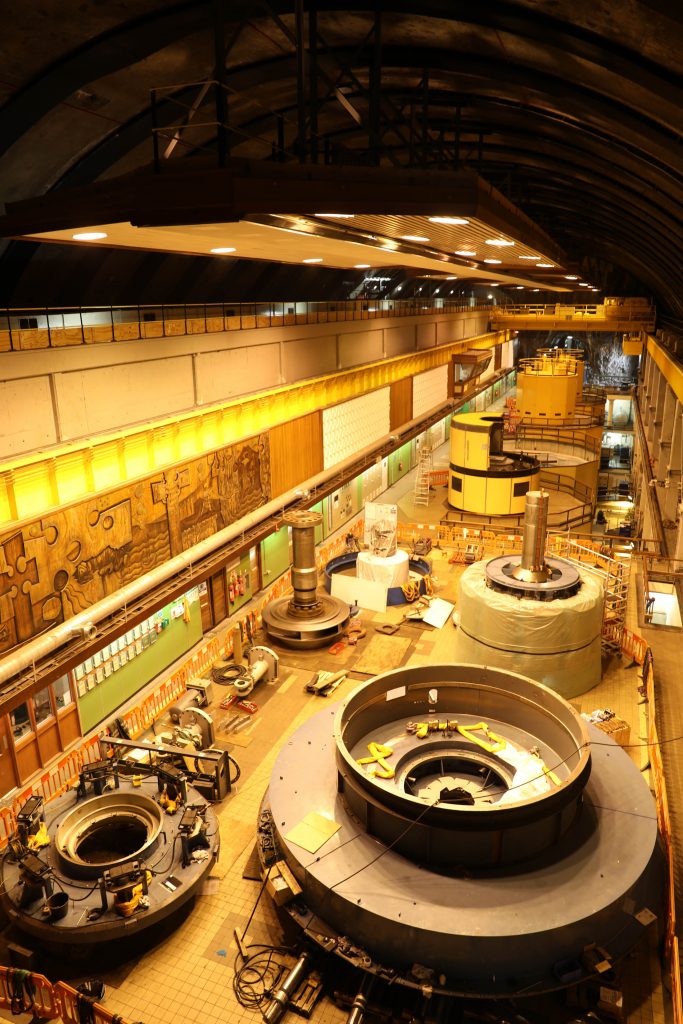
The mural within the Turbine Hall at Cruachan Power Station undergoing maintenance [November 2018]
The story claims the water washed a path through to the sea, creating the Pass of Brander. The site of a 1308 battle in the Scottish Wars of Independence, where Robert the Bruce defeated the English-aligned MacDougall and Macnaghten clans.
The mythical first section of the mural is separated by a Celtic-style cross from the modern second segment, which portrays the power station’s construction within Ben Cruachan. Here, four figures represent the four lead engineers of the project from the firms James Williamson & Partners, William Tawse Ltd, Edmund Nuttall Ltd and Merz & McLellan. They stand by the mountain, a roughly cut path running through its core.
At the base of the mural are the faces of 15 men lying on their sides. These are the 15 who were killed in 1962 when the ceiling of the turbine hall caved in during construction. Their uniform expressionless faces, however, turn them into symbols of the 30-plus workers who died while digging and blasting the power station’s tunnels and constructing the dam at the upper reservoir.
Next to this is a fairy tale portrayal of Queen Elizabeth II, who wears a gold grown and holds a sceptre from which electricity flows in a glowing lightning bolt through rock, commanding the power station into life.
The final third of the mural shows the whole power station system within the mountain. The upper reservoir sits nestled in the slopes of Ben Cruachan with water flowing down the mountain to the four turbines and Loch Awe below. Viewed as a whole, the mural takes the audience from mythology to the modern power station, which continues to play a vital role in the electricity system today.
The mural was created by artist Elizabeth Falconer, who was commissioned to create it to celebrate the power station’s opening by the Queen on 15 October 1965. At the time, only two of Cruachan’s four 100 megawatt (MW) reversible turbines were completed and operational, but it was still the first station of its kind to operate at such a scale. Two of the power station’s turbines were modified with increased capacities meaning Cruachan can both use and generate up to 440 MW.
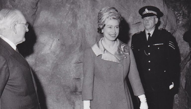
HRH Queen Elizabeth II opening Cruachan on 15 October 1965
The project came to Falconer through her husband, a native of Aberdeen who worked as an architect partner to one of Cruachan’s engineering firms. The brief simply requested she create a piece to fill the empty space on the wall of the turbine hall. Deciding to dive into the history and mythology of the mountain, she initially carved the mural in London and only ventured into Hollow Mountain years after it was first put in place, to make renovations on the work.
Cruachan Power Station was a visionary idea and represented a considerable technical and engineering achievement when it opened. The designs and construction of the reversable turbines put this site at the cutting end of modern energy technology.
So, it’s fitting the mural appears distinctly modern in its design, yet tells a story that connects this modern power station to the ancient rock it lives within.
It’s Cruachan’s mural’s location inside the mountain that makes it so unique as a work of art. However, at a time when the electricity grid is changing to an increasingly renewable system, based more around weather and geography, the connections the mural makes between Scotland’s landscape and the modern power station, make it relevant beyond the turbine cavern.
We’re familiar with using natural gas every day in heating homes, powering boilers and igniting stove tops. But this same natural gas – predominantly methane – is also one of the most important sources of electricity to the UK. In 2019 gas generation accounted for 39% of Great Britain’s electricity mix. But that could soon be changing.
Hydrogen, the super simple, super light element, can be a zero-carbon emissions source of fuel. While we’re used to seeing it in everyday in water (H2O), as a gas it has been tested as an alternative to methane in homes and as a fuel for vehicles.
Could it also replace natural gas in power stations and help keep the lights on?
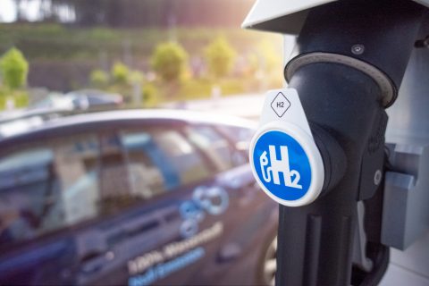
Hydrogen fuel station
Natural gas has been the largest single source of electricity in Great Britain since around 2000 (aside from the period 2012-14 when coal made a resurgence due to high gas prices). The dominance of gas over coal is in part thanks to the abundant supply of it in the North Sea. Along with carbon pricing, domestic supply makes gas much cheaper than coal, and much cleaner, emitting as much as 60% less CO2 than the solid fossil fuel.
Added to this is the ability of gas power stations to start up, change their output and shut down very quickly to meet sudden shifts in electricity demand. This flexibility is helpful to support the growth of weather-dependant renewable sources of power such as wind or solar. The stability gas brings has helped the country decarbonise its power supply rapidly.
Hydrogen, on the other hand, can be an even cleaner fuel as it only releases water vapour and nitrous oxide when combusted in large gas turbines. This means it could offer a low- or zero-carbon, flexible alternative to natural gas that makes use of Great Britain’s existing gas infrastructure. But it’s not as simple as just switching fuels.
Some thermal power stations work by combusting a fuel, such as biomass or coal, in a boiler to generate intense heat that turns water into high-pressure steam which then spins a turbine. Gas turbines, however, are different.
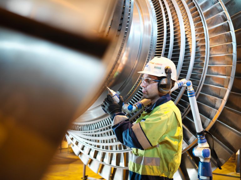
Engineer works on a turbine at Drax Power Station
Instead of heating water into steam, a simple gas turbine blasts a mix of gas, plus air from the surrounding atmosphere, at high pressure into a combustion chamber, where a chemical reaction takes place – oxygen from the air continuously feeding a gas-powered flame. The high-pressure and hot gasses then spin a turbine. The reaction that takes place inside the combustion chamber is dependent on the chemical mix that enters it.
“Natural gas turbines have been tailored and optimised for their working conditions,” explains Richard Armstrong, Drax Lead Engineer.
“Hydrogen is a gas that burns in the same way as natural gas, but it burns at different temperatures, at different speeds and it requires different ratios of oxygen to get the most efficient combustion.”
Switching a power station from natural gas to hydrogen would take significant testing and refining to optimise every aspect of the process and ensure everything is safe. This would no doubt continue over years, subtly developing the engines over time to improve efficiency in a similar way to how natural gas combustion has evolved. But it’s certainly possible.
What may be trickier though is providing the supply of hydrogen necessary to power and balance the country’s electricity system.
Hydrogen is the most abundant element in the universe. But it’s very rare to find it on its own. Because it’s so atomically simple, it’s highly reactive and almost always found naturally bonded to other elements.
Water is the prime example: it’s made up of two hydrogen atoms and one oxygen atom, making it H2O. Hydrogen’s tendency to bond with everything means a pure stream of it, as would be needed in a power station, has to be produced rather than extracted from underground like natural gas.
Hydrogen as a gas at standard temperature and pressure is known by the symbol H2.
A power station would also need a lot more hydrogen than natural gas. By volume it would take three times as much hydrogen to produce the same amount of energy as would be needed with natural gas. However, because it is so light the hydrogen would still have a lower mass.
“A very large supply of hydrogen would be needed, which doesn’t exist in the UK at the moment,” says Rachel Grima, Research & Innovation Engineer at Drax. “So, at the same time as converting a power plant to hydrogen, you’d need to build a facility to produce it alongside it.”
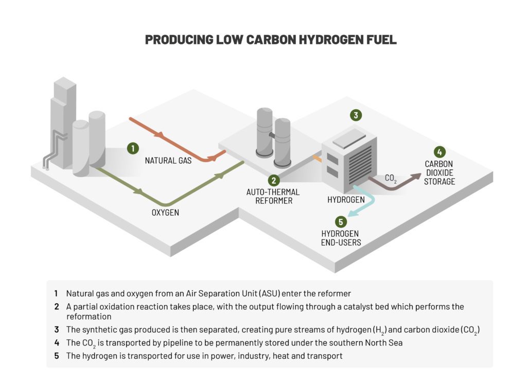
One of the most established ways to produce hydrogen is through a process known as steam methane reforming. This applies high temperatures and pressure to natural gas to break down the methane (which makes up the majority of natural gas) into hydrogen and carbon dioxide (CO2).
The obvious problem with the process is it still emits CO2, meaning carbon capture and storage (CCS) systems are needed if it is to be carbon neutral.
Source: Zero Carbon Humber
“It’s almost like capturing the CO2 from natural gas before its combusted, rather than post-combustion,” explains Grima. “One of the advantages of this is that the CO2 is at a much higher concentration, which makes it much easier to capture than in flue gas when it is diluted with a lot of nitrogen.”
Using natural gas in the process produces what’s known as ‘grey hydrogen’, adding carbon capture to make the process carbon neutral is known as ‘blue hydrogen’ – but there are ways to make it with renewable energy sources too.
Electrolysis is already an established technology, where an electrical current is used to break water down into hydrogen and oxygen. This ‘green hydrogen’ cuts out the CO2 emissions that come from using natural gas. However, like charging an electric vehicle, the process is only carbon-neutral if the electricity powering it comes from zero carbon sources, such as nuclear, wind and solar.
It’s also possible to produce hydrogen from biomass. By putting biomass under high temperatures and adding a limited amount of oxygen (to prevent the biomass combusting) the biomass can be gasified, meaning it is turned into a mix of hydrogen and CO2. By using a sustainable biomass supply chain where forests absorb the equivalent of the CO2 emitted but where some fossil fuels are used within the supply chain, the process becomes low carbon.
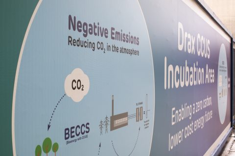
Carbon capture use and storage (CCUS) Incubation Area, Drax Power Station
CCS can then be added to make it carbon negative overall, meaning more CO2 is captured and stored at forest level and in below-ground carbon storage than is emitted throughout its lifecycle. This form of ‘green hydrogen’ is known as bioenergy with carbon capture and storage (BECCS) hydrogen or negative emissions hydrogen.
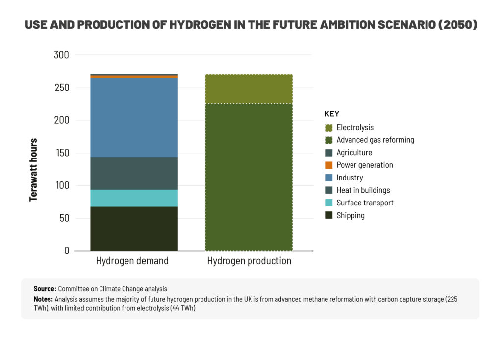
There are plenty of options for making hydrogen, but doing it at the scale needed for power generation and ensuring it’s an affordable fuel is the real challenge. Then there is the issue of transporting and working with hydrogen.
“The difficulty is less in converting the UK’s gas power stations and turbines themselves. That’s a hurdle but most turbine manufacturers already in the process of developing solutions for this,” says Armstrong.
“The challenge is establishing a stable and consistent supply of hydrogen and the transmission network to get it to site.”
Today hydrogen is mainly transported by truck as either a gas or cooled down to minus-253 degrees Celsius, at which point it becomes a liquid (LH2). However, there is plenty of infrastructure already in place around the UK that could make transporting hydrogen significantly more efficient.
“The UK has a very advanced and comprehensive gas grid. A conversion to hydrogen would be more economic if you could repurpose the existing gas infrastructure,” says Hannah Steedman, Innovation Engineer at Drax.
“The most feasible way to feed a power station is through pipelines and a lot of work is underway to determine if the current natural gas network could be used for hydrogen.”

Hydrogen is different to natural gas in that it is a very small and highly reactive molecule, therefore it needs to be treated differently. For example, parts of the existing gas network are made of steel, a metal which hydrogen reacts with, causing what’s known as hydrogen embrittlement, which can lead to cracks and failures that could potentially allow gas to escape. There are also factors around safety and efficiency to consider.
Like natural gas, hydrogen is also odourless, meaning it would need to have an odourant added to it. Experimentation is underway to find out if mercaptan, the odourant added to natural gas to give it a sulphuric smell, is also compatible with hydrogen.
But for all the challenges that might come with switching to hydrogen, there are huge advantages.
The UK’s gas network – both power generation and domestic – must move away from fossil fuels if it is to stop emitting CO2 into the atmosphere, and for the country to reach net zero by 2050. While the process will not be as simple as switching gases, it creates an opportunity to upgrade the UK’s gas infrastructure – for power, in homes and even as a vehicle fuel.
Source: Zero Carbon Humber
It won’t happen overnight, but hydrogen is a proven energy fuel source. While it may take time to ramp up production to a scale which can meet demand, at a reasonable cost, transitioning to hydrogen is a chance to future-proof the gas systems that contributes so heavily to the UK’s stable power system.

Carbon capture and storage (CCS) is the process of trapping or collecting carbon emissions from a large-scale source – for example, a power station or factory – and then permanently storing them.
Carbon capture usage and storage (CCUS) is where captured carbon dioxide (CO2) may be used, rather than stored, in other industrial processes or even in the manufacture of consumer products.
Carbon can be captured either pre-combustion, where it is removed from fuels that emit carbon before the fuel is used, or post-combustion, where carbon is captured directly from the gases emitted once a fuel is burned.
Pre-combustion carbon capture involves solid fossil fuels being converted into a mixture of hydrogen and carbon dioxide under heat pressure. The separated CO2 is
captured and transported to be stored or used.
Post-combustion carbon capture uses the addition of other materials (such as solvents) to separate the carbon from flue gases produced as a result of the fuel being burned. The isolated carbon is then transported (normally via pipeline) to be stored permanently – usually deep underground – or used for other purposes.
Carbon capture and storage traps and removes carbon dioxide from large sources and most of that CO2 is not released into the atmosphere.
Once carbon is captured it can be stored permanently or used in a variety of different ways. For example, material including carbon nanofibres and bioplastics can be produced from captured carbon and used in products such as airplanes and bicycles, while several start-ups are developing methods of turning captured CO2 into animal feed.
Captured carbon can even assist in the large-scale production of hydrogen, which could be used as a carbon-neutral source of transport fuel or as an alternative to natural gas in power generation.

Carbon can be stored in geological reserves, commonly naturally occurring underground rock formations such as unused natural gas reservoirs, saline aquifers, or ‘unmineable’ coal beds. The process of storage is referred to as sequestration.
The underground storage process means that the carbon can integrate into the earth through mineral storage, where the gas chemically reacts with the minerals in the rock formations and forms new, solid minerals that ensure it is permanently and safely stored.
Carbon injected into a saline aquifer dissolves into the water and descends to the bottom of the aquifer in a process called dissolution storage.
According to the Global CCS Institute, over 25 million tonnes of carbon captured from the power and industrial sectors was successfully and permanently stored in 2019 across sites in the USA, Norway and Brazil.
CO2 is a greenhouse gas, which traps heat in our atmosphere, and therefore contributes to global warming. By capturing and storing carbon, it is being taken out of the atmosphere, which reduces greenhouse gas levels and helps mitigate the effects of climate change.

The national grid, or simply the grid, is the network of powerlines, pylons, gas lines and interconnectors that makes up Great Britain’s electricity and gas systems — and the engineers, technology and rules responsible for their seamless operation. It ensures electricity generated anywhere, by any source, can be transmitted to meet the demand for power wherever it’s needed across the country. It heats homes and businesses. It helps us to cook our food.
The national electricity grid consists of a high voltage transmission system, which connects electricity from power stations to substations and smaller local networks – called Distribution Network Operators, or DNOs – which transport electricity into homes and businesses.

Transporting electricity around the grid is more complicated than just connecting cables to power generators. In order to move power around the country, things like voltage and frequency of electricity must be balanced and kept uniform at all times. Without this, unstable electricity could damage equipment and ultimately lead to blackouts.
The National Grid Electricity System operator (ESO) is a separate entity from the National Grid company, and is responsible for maintaining the correct voltage, frequency and reserve power levels to ensure electricity is transmitted safely and efficiently at all times.
It does this by working with power generators and energy storage facilities to provide what are known as ‘ancillary services’ – a set of processes that keep the power system in operation, stable and balanced.
The national grid is the network of power stations, powerlines and electricity infrastructure that allows electricity to be generated, transported and used across the country.
In Great Britain the National Grid company owns and operates the transmission systems which ensure electricity is delivered safely and reliably across the country.
The local distribution system is made up of 14 regional DNO companies, which deliver electricity at a lower voltage from substations to homes and businesses.
Great Britain’s grid incudes England, Scotland, Wales and several surrounding islands. Northern Ireland is part of an island-wide electricity system with the Republic of Ireland.
As the sources that generate Great Britain’s electricity change to include more renewables, the grid has also changed.
The grid was built to work with large power stations that operate huge spinning turbines. With decarbonisation it’s evolved to include a greater variety of intermittent weather dependent sources such as wind, solar and decentralised power sources that serve individual buildings or communities.
This makes managing the grid’s stability more complicated, and requires the use of more ancillary services, usually delivered by flexible generators such as thermal power stations.

Decarbonisation is the term used for the process of removing or reducing the carbon dioxide (CO2) output of a country’s economy. This is usually done by decreasing the amount of CO2 emitted across the active industries within that economy.
Currently, a wide range of sectors – industrial, residential and transport – run largely on fossil fuels, which means that their energy comes from the combustion of fuels like coal, oil or gas.
The CO2 emitted from using these fuels acts as a greenhouse gas, trapping in heat and contributing to global warming. By using alternative sources of energy, industries can reduce the amount of CO2 emitted into the atmosphere and can help to slow the effects of climate change.

There are numerous greenhouse gases that contribute to global warming, however CO2 is the most prevalent. As of 2018, carbon levels are the highest they’ve been in 800,000 years.
The Paris Agreement was created to hold nations accountable in their efforts to decrease carbon emissions, with the central goal of ensuring that temperatures don’t rise 2 degrees Celsius above pre-industrial level.
With 195 current signatories, economies have begun to factor in the need for less investment in carbon, with the UK leading the G20 nations in decarbonising its economy in the 21st century.
There are numerous energy technologies that aim to reduce emissions from industries, as well as those that work towards reducing carbon emissions from the atmosphere.
Decarbonisation has had the most progress in electricity generation because of the growth of renewable sources of power, such as wind turbines, solar panels and coal-to-biomass upgrades, meaning that homes and businesses don’t have to rely on fossil fuels. Other innovations, such as using batteries and allowing homes to generate and share their own power, can also lead to higher rates of decarbonisation. As the electricity itself is made cleaner, it therefore assists electricity users themselves to become cleaner in the process.
Other approaches, such as reforestation or carbon capture and storage, help to pull existing carbon from the air, to neutralise carbon output, or in some cases, help to make electricity generation – and even entire nations – carbon negative.
Alternative power options means that homes and businesses don’t have to rely on traditional carbon fuels.
For decarbonisation to be more widely adopted as a method for combating climate change, there needs to be structural economical change, according to Deloitte Access Economics. Creating more room for decarbonisation through investing in alternative energies means that “there are a multitude of job-rich, shovel-ready, stimulus opportunities that also unlock long-term value”.
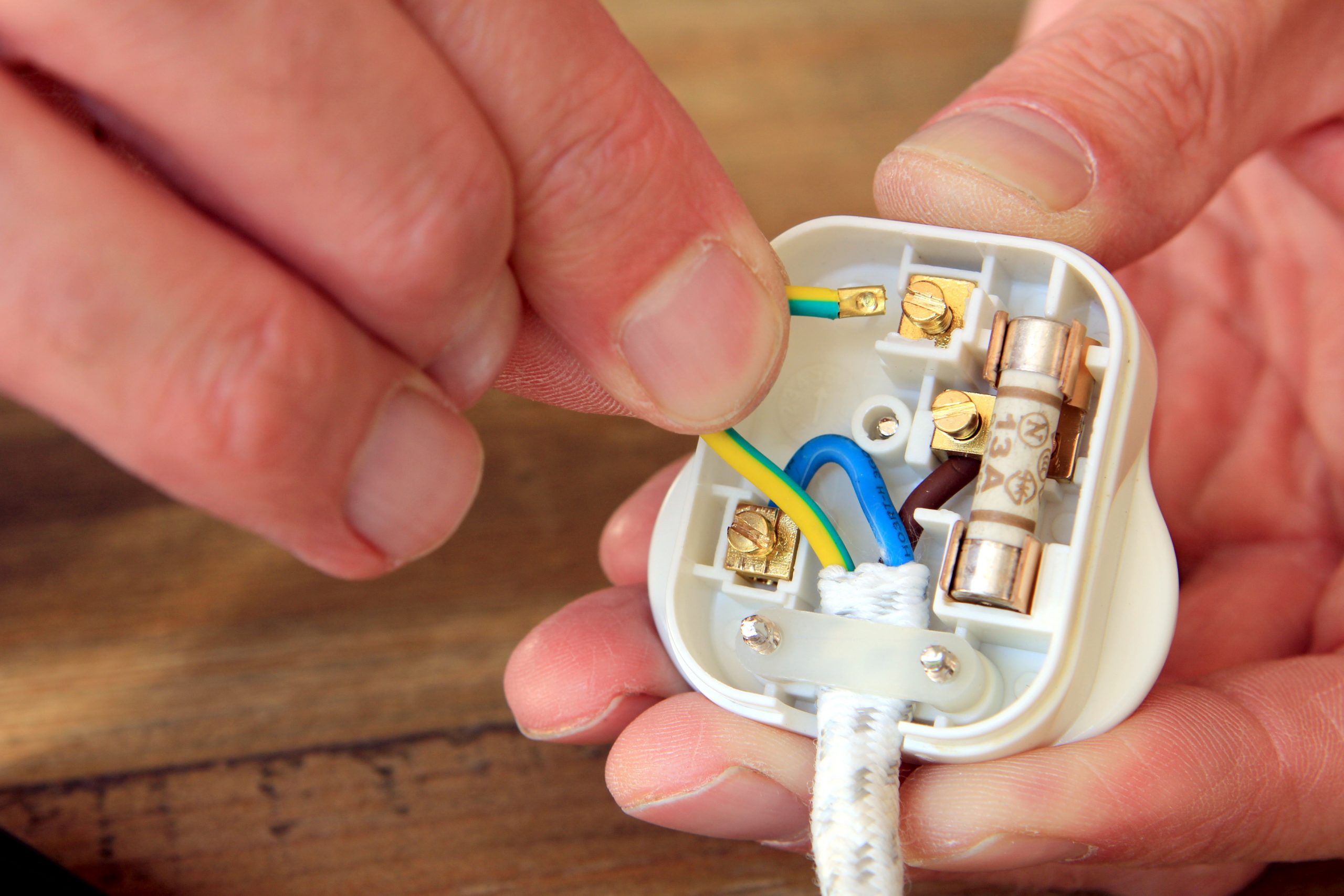
It may be bulkier than its foreign cousins and its flat back might make it the perfect household booby trap, but the UK plug is a modern-day design marvel.
The UK’s ‘G Type’ (or BS 1363) plug is a product of the post-war age. But it has endured for the better part of a century, ensuring homes, business and sockets around the UK have access to safe, usable electricity. Even as the devices they power have changed, become smarter and more connected, the three-prong G Type remains unchanged.
But to understand how it came into being, it’s worth first understanding what makes it such a unique and clever bit of design – including its role in achieving the ambitions of one of Great Britain’s pioneering female engineers, and its money-saving abilities.
The modern plug used across Great Britain (as well as Ireland, Cyprus, Hong Kong and Malaysia) is a smarter and more advanced item than many of its contemporaries. This is thanks to a number of key, but often overlooked, features.
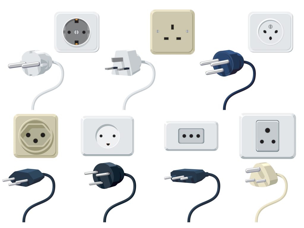
A collection of international power point illustrations
The first is its earth prong. Connecting the plug to the earth means if a wire comes loose in, say, a toaster and touches a metal part, the device will short circuit as the electricity runs through to make contact with the earth, rather than the entire item becoming electrified and dangerous.
The longer earth prong also plays the role of ‘gatekeeper’ for the entire plug. When a plug enters a socket the longer earth prong enters before any others, pushing back plastic shutters that sit over the live and neutral entrances. This means when there is no plug in a socket the live and neutral ports, which actually carry electric current to devices, are covered over making it very difficult for a child to push anything dangerous into the socket.
Another clever feature inside the Great British plug comes in the form of a fuse connected to the live wire. If there’s an unexpected electrical surge the fuse will blow and cut off the connected device, preventing fires and electrocutions.All packaged together, the G Type plug is far from the most compact version – yet it is hugely effective. However, these ideas didn’t come together at the flick of a switch.
Going back to end of the 19th Century, the idea of owning devices you could move around your house and connect to the electricity circuit from different rooms was novel.
Electricity’s main role in homes was for lighting and was fixed into walls and ceilings, with their cables hidden. It wasn’t until the rise of new electrical appliances in the 20th century that the need for an easy way to plug electrical items into circuits arose.
A series of two-pronged plugs first emerged in 1883, but there was no standardisation of design which would allow any appliance to be plugged into any socket. That began to change in 1904, when US inventor Harvey Hubbell developed a plug that allowed non-bulb electrical devices to be connected into an existing light socket, eliminating the need for the installation of new sockets.
By 1911, a design for a three-pronged plug with an earth connection had emerged, with manufacturer AP Lundberg bringing the first of this kind of plug to Britain.
By 1934, regulations appeared requiring plugs and sockets to include an earthing prong, which eventually gave birth to a three, cylindrical-pronged plug: the BS 546.
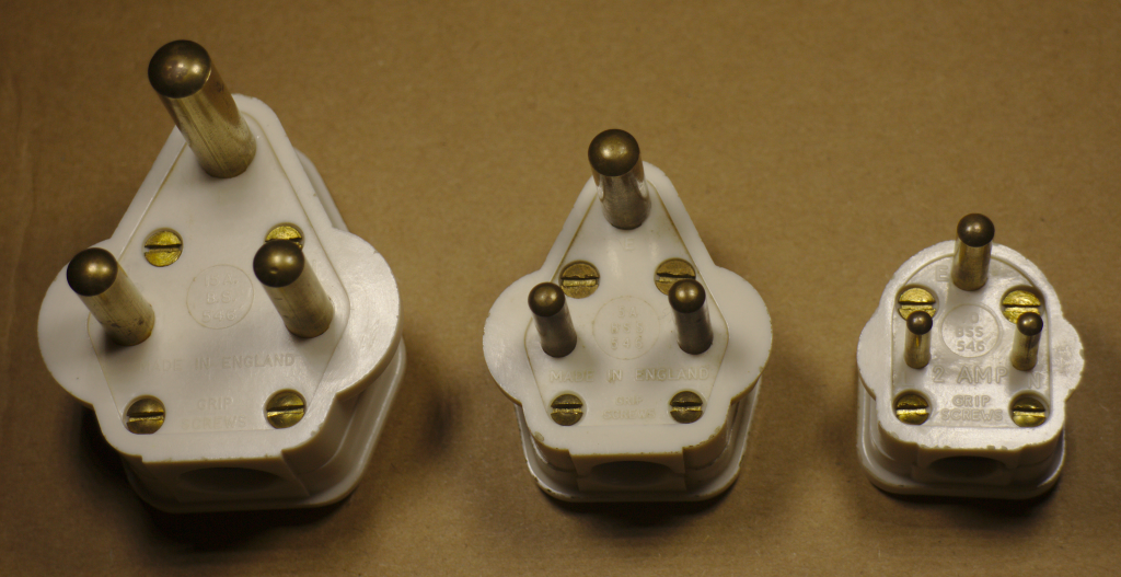
BS 546 plugs
The BS 546 was different from the modern G-Type as they didn’t contain a fuse and were available in five different sizes depending on the needs of the appliance, from small 2 ampere plugs for low-power appliances to a larger 30 ampere version for industrial machinery. The different sizes and spacing of the prongs prevented low-power devices accidentally being plugged into high-power outlets.
Any chance of globally standardising plugs was doomed from the beginning, as different companies in different countries all began developing their own plugs for their products as electricity rapidly gained uptake.
Some attempts were made by the International Electrotechnical Commission (IEC) to standardise plugs globally but the Second World War put a stop to any progress.
Great Britain emerged from the Second World War with its national grid standing strong. The challenge now was to make electricity not just the power source of factories and wealthy people’s homes, but something available for everyone in the wave of new post-war construction.
Other countries, not seeing as much damage to their housing stock as the UK, did not have the same opportunity to rethink domestic electricity to such an extent. Therefore, the Institution of Electrical Engineers (IEE) assembled a 20-person committee to consider the electrical requirements of the country’s new homes.

Breaking new ground: Caroline Haslett
The sole woman on the committee, Caroline Haslett, had been breaking new ground for female engineers since before World War One. In her career she worked with turbine inventor Charles Parsons and his wife (an engineer in her own right) and in 1932 became the first woman selected to join the IEE. Her passion for electricity went so far as for her will to request she be cremated via electricity.
She had long believed in the potential for domestic electricity to improve women’s lives by freeing them from the drudgery of pre-electric domestic chores, from handwashing clothes to cooking on coal-fuelled stoves. This included ensuring electricity was safe for the people using electricity around the home which in the 1940s was primarily women, who also did the vast majority of childcare.
Haslett’s drive to make electricity safe in the home was pivotal in shaping many of the IEE’s safety requirements for post-war domestic electricity, including what have become the country’s standard plugs and sockets.
There was another factor aside from safety at play. The material cost of the war meant copper, the main material used in electrical wiring, was in short supply, so the IEE came up with a new way of wiring homes that would in turn shape our plugs.
Before the war, British sockets were all separately wired back to a central fuse box. It made sense, because if something went wrong only the fuse connected to that socket would blow rather than the whole house.
However, to cut the amount of copper used the IEE instead proposed a clever workaround where the home’s electrical sockets are looped up in one Ring Circuit, with the fuses moved to the plugs themselves. So, if something went wrong in an appliance the fault would stop at the plug, where the fuse could easily be accessed and replaced. Lighting fixtures remained wired in a separate circuit from sockets as they require less current to operate.

Copper was short in supply during World War Two.
This hidden fuse, is a big differentiator from other plug types and adds to the G Type’s safety credentials. However, the IEE had to ensure people did not mistakenly insert older three-prong BS 546 plug styles without fuses into the sockets.
The answer was as simple as switching the socket holes from round to rectangle. It means the older round cylinder prongs wouldn’t fit into the slot designed for the rectangles found on plugs today.
The G Type plug might seem cumbersome compared to the European or US models, but in the 70-plus years since its introduction its three prongs and in-built fuse, has proved an enduring design that can power new devices and smart technology, while remaining one of the safest plugs in the world.

How long do your electrical devices last? We’re not talking about battery life, but the overall lifetime of the items we use every day that are powered by electricity.
It’s accepted that today’s electrical devices have short life spans, in part a symptom of rapidly evolving technology fuelling the need for constant consumer updates and in part a result of planned obsolescence (devices being manufactured to fail within a set number of years to encourage repeat purchases). Electrical devices aren’t purchased with the belief they will last a lifetime.
But it hasn’t always been this way. Before rapid technological development and the rise of fast consumerism, devices were built to last.
Over the relatively short history of electrical appliances, there are tools and equipment that have operated for decades. Some of these remain in operation today with hardly any alterations, but for a few tweaks here and there to upgrade or preserve.
Built to last, here are a few of the longest running electrical inventions.
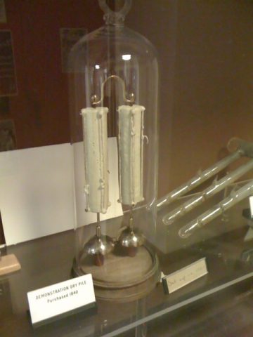
The Oxford Electric Bell located in the Clarendon Laboratory, University of Oxford.
The Oxford Electric Bell is not your typical bell – not just in how it looks, but in the fact it has been in constant operation since the mid 19th Century. It consists of two primitive batteries called ‘dry piles’ with bells fitted at each end and a metal ball that vibrates between them to very quietly, continuously ring.
Its original purpose is unidentified, but what is known is that the bell is the result of an experiment put on by the London instrument-manufacturing firm Watkins and Hill in 1840. Acquired by Robert Walker, a physics professor at the University of Oxford in the mid 1800s, it’s displayed at Oxford’s Clarendon Laboratory which explains why it’s also known as the Clarendon Pile.
The exact make-up of the dry piles is unknown, as no one wants to tamper with them to investigate their composition out for fear of ending the bell’s 179-year-long streak. As a result, confusion remains as to why The Oxford Electric Bell has remained in operation for so long.
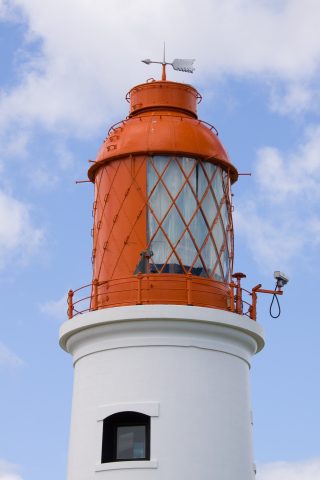
Souter Lighthouse, Tyneside, England.
The lamp in the Souter lighthouse, situated between the rivers Tyne and Wear, was the most advanced of its day when it was first constructed. Designed to use an alternating electric current, it was the first purpose-built, electrically powered lighthouse in the world. Although no longer in operation today, it ran unchanged for nearly 50 years.
The light was generated using carbon arc lamps, and it originally produced a beam of red light that would come on once every five seconds.
Souter’s original lamp operated unchanged from 1871 to 1914, when it was replaced by more conventional oil lamps. It was altered again to run on mains electric power in 1952 and was finally deactivated in 1988.
Tourism hit the Isle of Man in the 1880s and with it came the construction of hotels and boarding houses. Two businessmen saw this as an opportunity to purchase a large estate on the island and develop it into housing and a pleasure development. The Manx Parliament approved the sale in 1892 on one condition: that a road and a tramway be built to give people access.
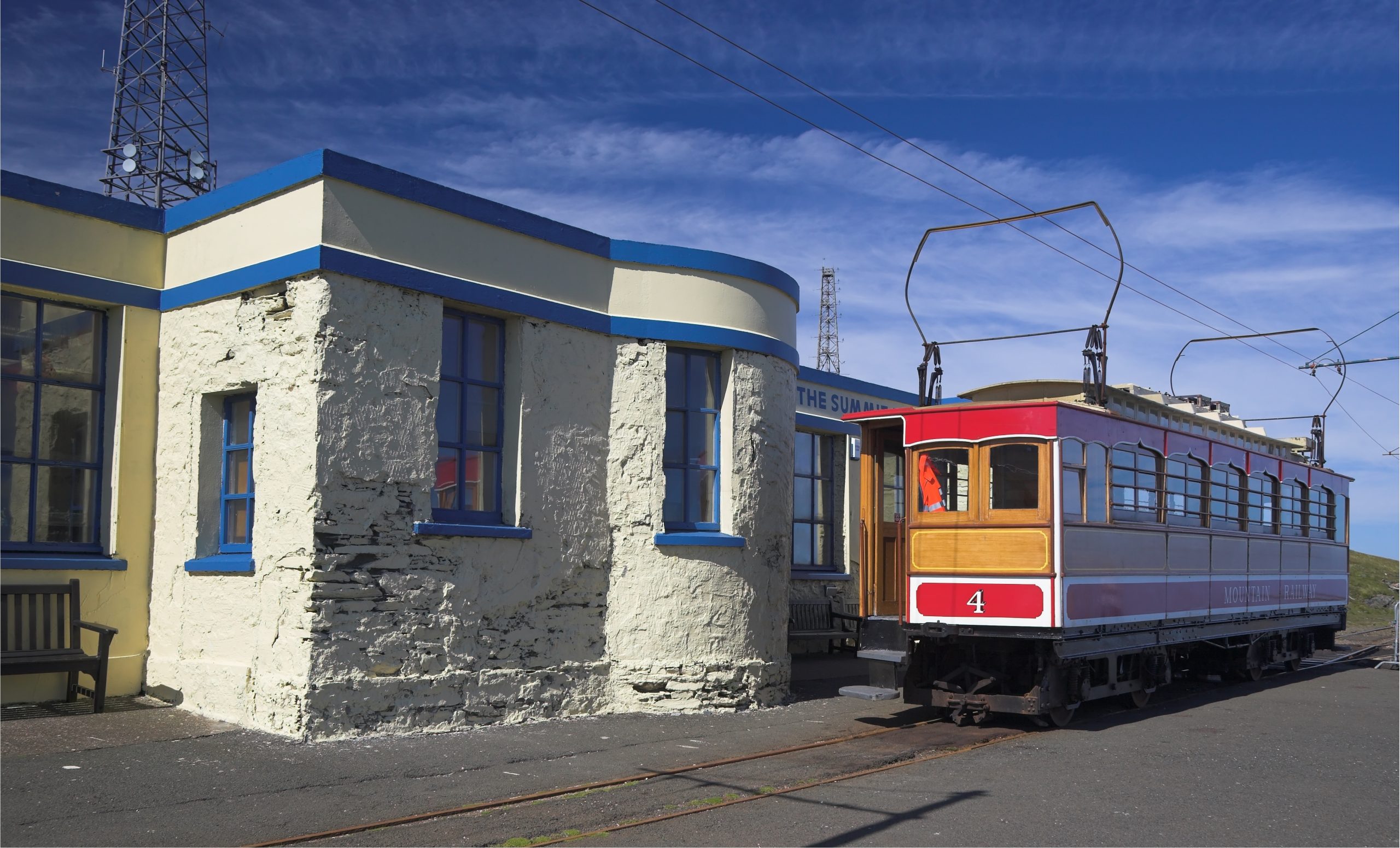
Snaefell mountain railway station, Isle of Man.
It was decided that the tram would be electric, and work began in the spring of 1893, with the tram system up and running by September of that year. Although the track and its cars have been extended and updated over time, the first three cars remain the longest running electric tramcars in the world.
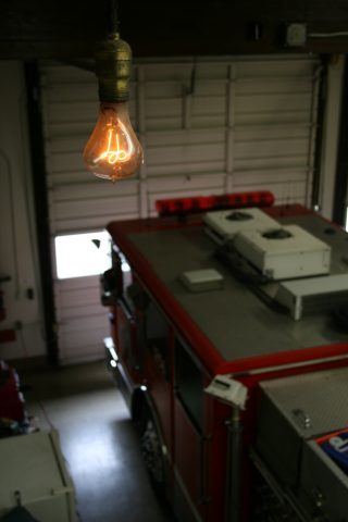
Photograph by Dick Jones (centennialbulb.org)
The unassuming Centennial Bulb has been working in the Livermore, California Fire Department for 117 years. The bulb was first installed in 1902 in the department’s hose cart house, but was later moved to Livermore’s Fire Station 6, where it has been illuminated for more than a million hours.
Throughout its life the Centennial Bulb has seen just two interruptions: for a week in 1937 when the Firehouse was refurbished, and in May 2013 when it was off for nine and a half hours due to a failed power supply. Made by the Shelby Electric Company, the hand-blown bulb previously shone at 60 watts but has since been dimmed to 4 watts.
While this means it isn’t able to actually illuminate much, it is a reminder that despite the disposable nature of many modern electrical devices, it’s possible to build electrical items that last.

As we head into the 2020s, it’s an exciting time for energy. A deeper level of climate consciousness has led to crucial changes in populations’ attitudes and thinking around how we power our lives – adapting to a new set of energy standards has become essential.
It’s also driving innovation in energy technology, leading to the rise of a number of emerging technologies designed to support the global energy transition in new ways. From domestic solar and wind generation, to leaps forward in recycling and aeroplane fuel, here are five new energy ideas in the 2020s pipeline.
Think of a wind farm and you might think of giant structures located in remote, windswept areas, but that’s quickly changing.
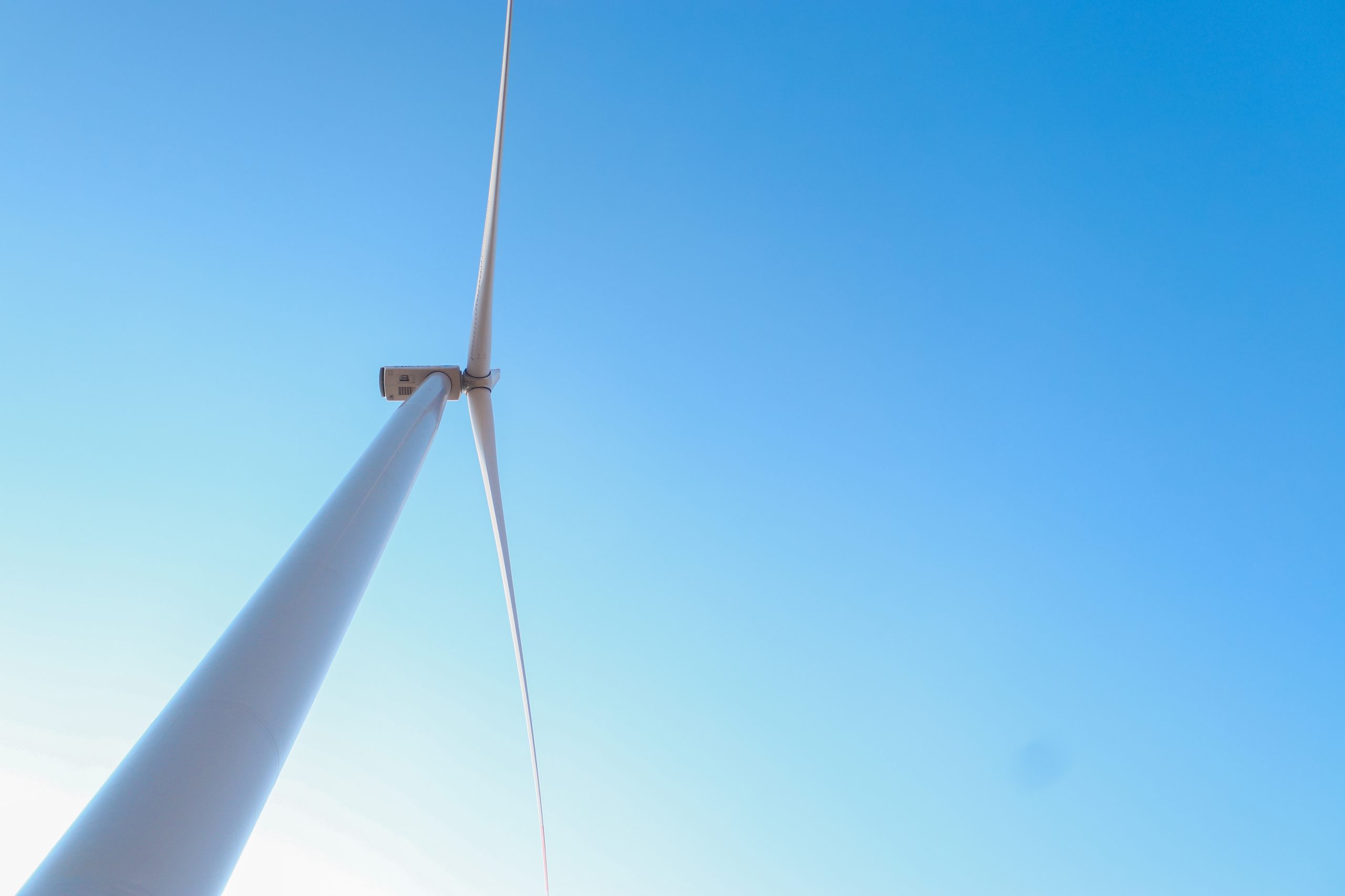
IceWind is developing residential wind turbines that use the same generator-principal as large-scale wind farms, just on a much smaller scale. A set of three outer and three inner vertical blades rotate when the wind passes through them, providing spinning mechanical energy that passes through the generator and is converted to electricity.
Constructed from durable stainless steel, carbon fibre and aluminium, the CW1000 model can handle wind speeds of up to 134 miles per hour. To ensure they’re fit for domestic use, the units are adapted to have a maximum height of just over 3 metres and make less than 40 decibels of noise – roughly equivalent to quiet conversation.
The Icelandic company says it aims to decentralise and democratise energy generation by making wind power accessible to people anywhere in the world.

As solar technology becomes more widespread and easier to implement, more communities are turning to a prosumer approach and generating their own power.
Roof panels to date have been the most common way to domestically capture and convert rays, but Solecco is taking it a step further, offering solar roof tiles. These work in the same way as roof panels, using photovoltaic cells made of silicon to convert sunlight into electricity. But by covering more surface area, entire roofs can be used to generate solar energy, rather than single panels.
Environmental Street Furniture takes it a step further by bringing small scale solar generation into many aspects of the urban environment such as smart benches, rubbish bins, and solar lighting in green spaces. This opens up opportunities for powering cities, including incorporating charging stations and network connectivity, which in turn enables social power sharing.
Global recycling rates currently sit at approximately 18%, indicating there are still further steps to take in ensuring single-use products are eliminated.
Plastic is a major target in the war on disposal, and for good reason. By 2015, the world had produced over seven billion tonnes of plastic. Greenology is tackling this by harnessing a process called pyrolysis to turn plastic into power. By heating waste at a very high temperature without oxygen, the plastic is breaks down without combusting.

This process produces bio-oils, which can be used to create biofuels. The benefits of this innovative approach to waste are twofold: not only can plastic be repurposed, which minimises the lasting impact single-use plastic has on the planet, but the creation of biofuel offers a power source for everything from transport to generating electricity.

Decarbonising heating is one of the global challenges yet to have a clear answer. Pumped Heat Ltd (PHL) is developing a potential solution with its heat battery technology. The company has found a solution that enables its devices to charge up and store electricity during ‘off-peak’ hours (when electricity is at its cheapest) and then use this energy to generate heating and hot water for homes as it is required. As the grid continues to decarbonise, and as renewable power becomes cheaper and more accessible, the electricity used to charge these units will approach zero carbon content.
The heat battery technology utilises vacuum insulation, losing 10 times less heat than a conventional night storage heater. In contrast, air sourced heat pumps (a more commonly used type of heat pump), operate in real time when a home needs heating. They take water at its delivery temperature (which can be very cold, during the winter months) and heat it using electricity available at that time. Pumped Heat’s storage system instead ensures there is always heat available, maintaining a consistent temperature for hot water or central heating, rather than just when there is an excess of electricity.
The company claims the benefit of using a heat battery system is that it is cheaper than an oil or LPG boiler, in a world where renewable electricity production, both domestic and on a national level, is only set to increase.
As some of the most fossil fuel-reliant industries in the world, travel and transport are actively seeking alternative and more sustainable ways to keep them powered in long run.

Velocys aims to do this using waste. The company is developing sustainable fuels for aviation and heavy goods transport, using the Fischer-Tropsch method of gasifying waste. This involves turning waste materials – such as domestic refuse and woody waste – into clean jet fuel using a catalytic chemical reaction, where synthesis gases (carbon monoxide and hydrogen) are converted into liquid hydrocarbons that can then be used for fuel.
Not only does this make use of waste products that could have ended up in landfill, but it produces much cleaner fuels, that emit less particle matter and harmful pollutants into the atmosphere.
As we enter a new decade of invention, the world is focusing on more sustainable alternatives to power our lives, and these innovative solutions to current environmental issues will continue to inspire creativity.